3U VPX Radar Reference Design
Extreme Engineering Solutions (X-ES) delivers VPX systems and high-performance, SOSA-aligned, embedded compute modules designed for rapid integration into mission-critical applications. The XPand1007 combines X-ES CPU-based compute platforms with purpose-selected SDR and GPGPU technologies from specialized industry partners to deliver a complete, integrated radar processing stack.
The result is a rapid development platform that enables customers to prototype, evaluate, and mature advanced sensing capabilities with minimal integration risk. By leveraging a modular ecosystem approach, X-ES provides a clear path from early development on the XPand1007 platform to deployment within rugged XPand6200 Series systems while preserving software investment and accelerating time to field, without requiring re-architecture at each transition.
Meet the Platform
Introduction to the 3U VPX Radar System
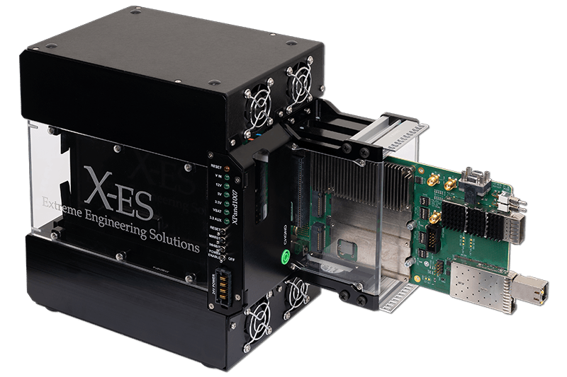
The XPand1007 is X-ES’ benchtop 3U VPX development system.
It provides a SOSA-aligned OpenVPX™ backplane in a desktop form factor designed for rapid integration, evaluation, and software maturation before transitioning to a ruggedized deployed chassis like the X-ES XPand6200 Series.
Platform Specifications
| Form Factor | 3U VPX benchtop chassis |
| SOSA-Aligned OpenVPX™ Profiles | 14.6.11 & 14.6.13 Payload (Compute Intensive) |
| Slots | Two 3U VPX-REDI (VITA 48.2) |
| Backplane fabric | PCIe Gen 4 |
| Intended use | Prototype · Evaluate · Mature |
| Deployment path | XPand6200 Series rugged system |
Two-Slot 3U VPX Development Platform for Conduction-Cooled Modules with RTM I/O
Ecosystem Partners
Best-of-Breed RF and Compute:
Purpose-Integrated
X-ES takes a deliberate ecosystem approach: rather than developing every subsystem in-house, it integrates proven partner technologies for RF and GPU acceleration. The two partners in this demonstration each bring deep domain expertise and defense-qualified hardware that results in not just a one-off demo, but a model for how deployable mission systems can be assembled from interoperable partner building blocks.
EIZO Rugged Solutions
X-ES Partner · Orlando, Florida
X-ES works with EIZO Rugged Solutions to bring embedded GPGPU acceleration into the radar pipeline. EIZO Rugged Solutions specializes in high-performance, MIL-STD-compliant visual technology and computing for defense, aerospace, and industrial markets.
Based in Florida, they develop rugged graphics cards, AI-accelerated GPGPU boards, video encoders, and rugged monitors designed to operate in extreme environments for situational awareness and mission-critical applications.
AI acceleration
Rugged graphics encoding
Situational awareness
Contributes to this demo: Condor GR2S-AD5000 — compute acceleration and visualization
Epiq Solutions
X-ES Partner · Rolling Meadows, Illinois
X-ES also incorporates Epiq Solutions SDR technology to provide flexible RF generation and capture within the same platform. Epiq Solutions specializes in small form factor Software Defined Radio transceivers built for low Size, Weight, and Power (SWaP) environments.
Their products are fielded across defense, aerospace, and security applications for signal processing, cyber surveillance, and spectrum monitoring where off-the-shelf commercial SDR hardware is neither qualified nor compact enough.
Signal processing
Spectrum monitoring
Open systems approach
Contributes to this demo: Sidekiq™ Stretch — State-of-the-art wideband RF ingest and waveform generation
System — Component Composition
Multiple Modules Populated, One Coherent Platform
The XPand1007’s two 3U VPX payload slots are populated with an X-ES Single Board Computer for control, the Epiq Sidekiq Stretch for RF, and the EIZO Condor GR2S-AD5000 for GPU acceleration. Each card is independently replaceable without chassis or software redesign.
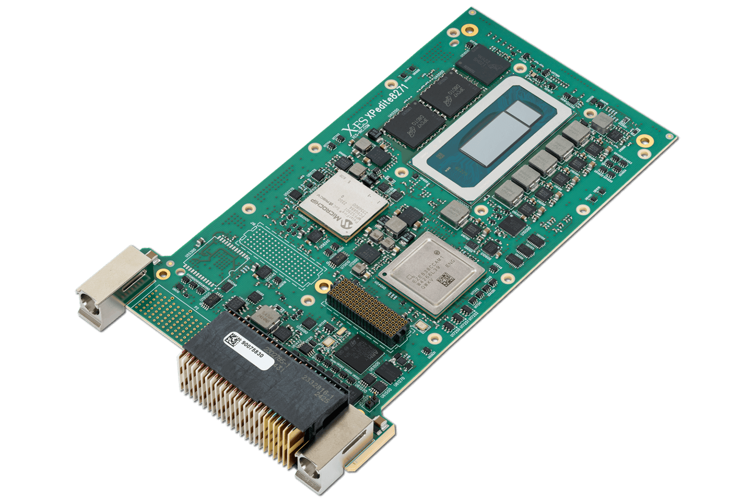
XPedite8271
13th Gen Intel® Core™ i7 Processor-Based 3U VPX-REDI Single Board Computer with 64 GB of LPDDR5 and Microchip PolarFire™ SoC FPGA.
- Host processor that orchestrates all system functions.
- Manages timing, scheduling, waveform selection, and deterministic data movement between the SDR and GPU over PCIe.
Role: Control plane + data orchestration
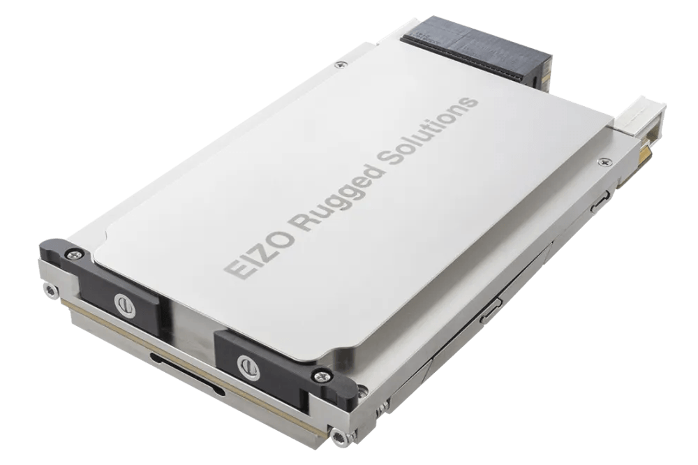
Condor GR2S-AD5000
3U OpenVPX™ video graphics and GPGPU processing module featuring the NVIDIA RTX™ 5000 Ada Generation GPU.
- Accelerates range-Doppler processing, visualization, and AI-enhanced tracking.
- GPU-resident Holoscan compute graphs.
Role: Compute acceleration + visualization
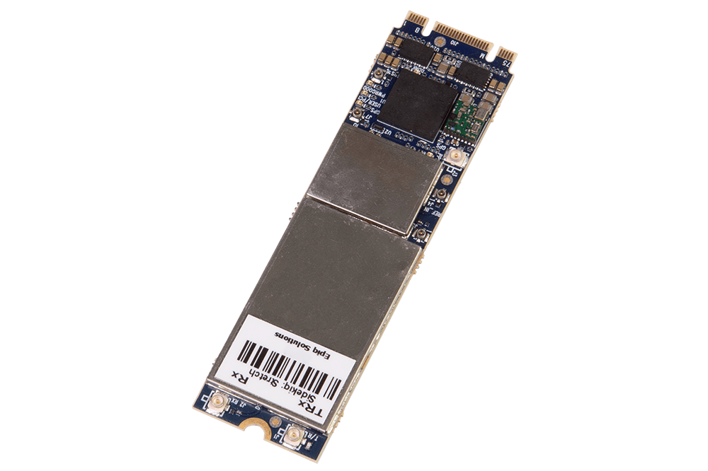
Sidekiq™ Stretch
Wideband RF transceiver with integrated FPGA, GPS, and integrated pre-select filters delivering low latency connectivity.
- Generates and captures I/Q samples for pulsed and FMCW waveforms across a wide RF tuning range.
- Controlled via SoapySDR for hardware-agnostic device abstraction.
Role: RF ingest + waveform generation
Architecture
Why VPX — and How the Modules Connect
The VPX Design Rationale
VPX/OpenVPX™ provides a rugged, high-bandwidth switched fabric that physically and electrically connects compute, RF, and acceleration in a single chassis.
The SOSA standards-aligned slot profiles mean the same backplane that runs this demo can host different vendor cards without re-cabling or chassis redesign.
Fabric
PCIe Gen4 between slots — sufficient bandwidth for streaming I/Q and GPU frame data without off-board bottlenecks.
SOSA Alignment
Standardized slot profiles allow module substitution across vendors. Lab and field systems share the same backplane topology.
Reuse path
XPand1007 architecture maps directly to XPand6200 Series chassis — cooling and connectorization change, software does not.
Data Path:
SDR → CPU → GPU
I/Q samples stream from the Sidekiq™ Stretch to the XPedite8271 over PCIe. The CPU performs framing, timing correction, and metadata tagging before forwarding pulse or chirp buffers — via ZMQ transport — to the Holoscan consumer on the GPU.
Control Path:
CPU orchestrates All
The XPedite8271 holds the radar state machine — it selects waveforms, sets PRIs, configures SDR gain and center frequency via SoapySDR, and schedules GPU workloads.
This separation of control and data planes keeps latency deterministic and makes waveform switching a software operation with no hardware changes.
Software
End-to-End Dataflow
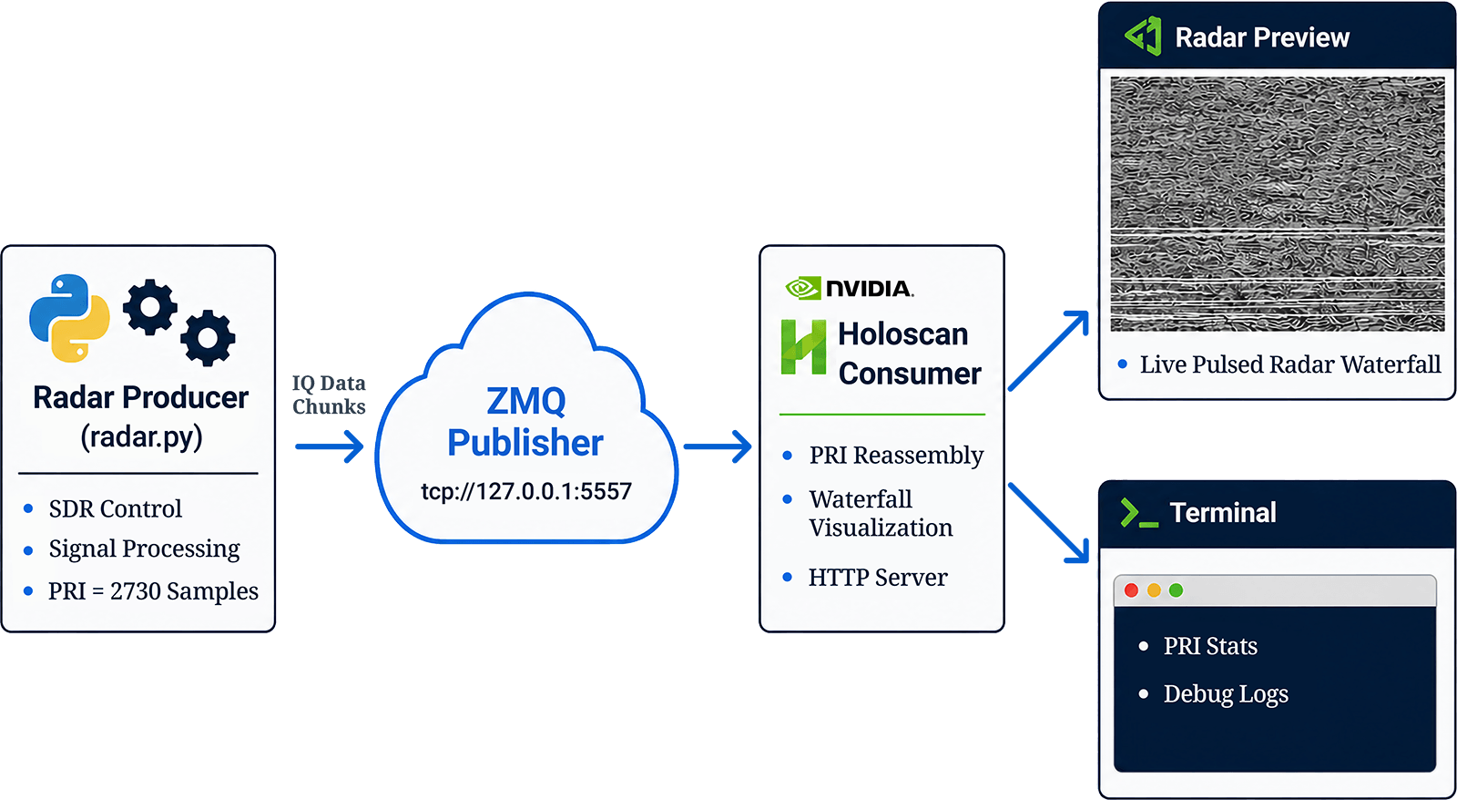
A four-layer pipeline connects SDR ingest to GPU visualization. ZMQ provides the inter-process transport between the radar producer and Holoscan consumer.
System Software Diagram
The radar producer (radar.py) handles SDR control, signal processing, and chunked I/Q data output at PRI = 2730 samples. Frames are published over ZMQ to the Holoscan consumer, which performs PRI reassembly, waterfall visualization, and exposes results via HTTP server. Terminal output provides PRI stats and debug logs.
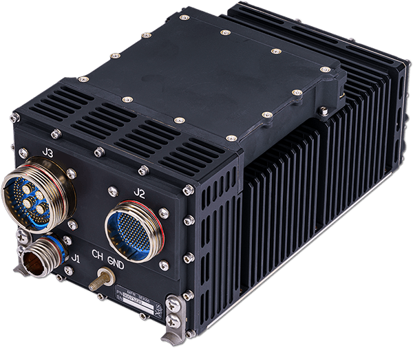
Deployment Path
From XPand1007 to XPand6200 Series Rugged System — Without Re-Architecture
Applications developed on the XPand1007 transition directly to XPand6200 Series ruggedized chassis. The software stack, device abstractions, and processing graphs carry over unchanged and only the physical packaging adapts.
What Changes After Transitioning
- Cooling method and ruggedization level.
- Backplane topology and fabric routing.
- I/O connectorization for deployed environment.
- Power budgets and environmental qualification.
What is Preserved After Transitioning
- SoapySDR device abstraction and SDR control logic.
- GNU Radio / custom DSP processing graphs.
- Holoscan GPU streaming and ZMQ transport layer.
- Full software investment — no re-architecture required.
Conclusion
Accelerating Radar System Development with X-ES
This demonstration highlights how X-ES delivers more than individual components—it provides a complete system architecture that enables rapid development and seamless transition to deployment. By combining X-ES SOSA-aligned compute solutions with partner SDR and GPGPU technologies, customers can quickly prototype advanced sensing applications while maintaining a clear path to rugged, fielded systems.
With the ability to move from XPand1007 development platforms to XPand6200 deployable systems with minimal software rework, X-ES reduces integration risk, shortens development timelines, and enables scalable, mission-ready solutions.
This approach aligns with modern defense acquisition priorities—modularity, reuse, and rapid capability delivery.
Ready to evaluate?
Contact X-ES to request a 3U VPX radar system demonstration or to discuss your sensing application.